Buck Converter Design Calculator Online
Vin 12 V VOUT 5 volts ILOAD 2 amps Fsw 400 KHz D V in Vout 5V 12V 0416 Define Ripple current. Component Calculator for BUCK Converters.
6 2 1 2 Buck Converter Component Calculator Open Circuit Institute

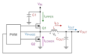
The synchronous buck converter is used to step a voltage down from a higher level to a lower level.
Buck converter design calculator online. When switching element Q 1 is ON current flows from V through the coil Land charges the output smoothing capacitor C O and the I O is supplied. Buck converter Figure 1 is the basic circuit of buck converter. Table 1 Specifications Input voltage 12 V Output voltage 18 V Maximum power 120 W Switching frequency 500 kHz.
To design a buck converter that will convert 12-volt input DC to 25-volt output with 1A. Buck Converter Design Example d. A buck converter delivering more than a few watts of power usually has multiple capacitors of the same type in parallel.
For such conversion we have some known data and some parameters are required. Automatic calculation of peripheral component parameters for three typical circuits Instructions Just enter the parameters you want in the left middle box and click the Calculate and refresh the circuit diagram button. All Rights Reserve Reserved.
The buck converter is a high efficiency step-down DCDC switching converter. This spreadsheet will calculate the values of the power stage components for a Buck switchmode power converter. Korak dol step down Tadej Kemperle.
This is necessary because some parameters for the calculations must be derived from the data sheet. Non-Isolated Buck Boost Buck-Boost Cuk SEPIC Isolated Push-pull Forward Flyback Half-Bridge. The highest expected input voltage.
The lowest desired. In this example we will calculate the required inductor and output c. Well derive the various equations for the current and voltage for a buck.
Trying to calculate the individual RMS currents for each device would be a nightmare. VLOFF VD VOUT 4 Using equations 2 and 4 the current flowing through coil L when Q1 is OFF is as follows. 2 Calculate the Maximum Switch Current.
Intro to SMPS Slide 3 3 Buck Converter Design Example Assumptions Assume. The lowest expected input voltage. If these parameters are known the power stage can be calculated.
Buck Converter Design 6 Design Note DN 2013-01 V01 January 2013 4 Design Equations The following are design equations for the CCM operated buck. Consequently ILP ILT 2 IOUT 6. This example will help to design buck converter.
The following is a design tool which calculates the parameters for a buck converter boost converter or Buck-Boost Converter - Step-downStep-up or invertingThe calculator assumes that during the normal load the inductor is in continuous mode meaning that the inductor. AHMAD ROSYID RIDLO_UNEJ_ELDA Sujanarko 2021_Buck-Boost Konverter. Wahyu Agung Bagus P_181910201067_Buck Converter_UNEJ_ELDA Sujanarko 2021.
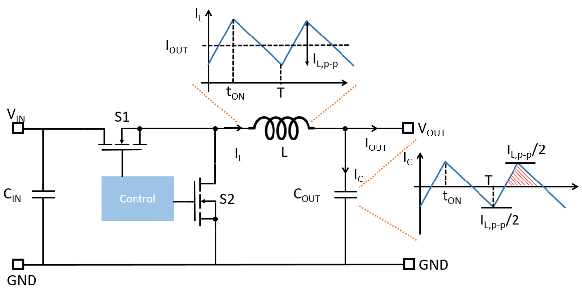
Inductor Calculation of Buck Converter From Fig. Rectangular pulses of voltage into an inductor result in a triangular current waveform. The user need only to fill in the input voltage output voltage load current switching frequency forward voltage drop of the rectifier and the.
Proper selection of components is must for successful conversion from 12v to 25 volt. Basic Calculation of a Buck Converters Power Stage Abstract This application note gives the formulas needed to design the power stage of a buck converter. DC-DC Converter Basics A circuit employing switching network that converts a DC voltage at one level to another DC voltage Two basic topologies.
Integrated circuit used to build the buck converter. The current which flows into the. This is the first part of a two-part set of videos illustrating the steps of the first run at designing a DC-DC buck converter.
This is the boost converter frequency. This application note describes how to determine the buck inductor and. Home How Tos Theory Power Electronics DC-DC Voltage Converters 6212 Buck Converter - Component Calculator 6212 Buck Converter - Component Calculator Input Parameters.
Switched mode power converters are very important in industry. Copy of Simple Buck Converter. For microcontrollers its often the CPU clock 256.
Capacitor Calculation for Buck converter IC This application note explains the calculation of external capacitor value for buck converter IC circuit. The converter uses a transistor switch typically a MOSFET to pulse width modulate the voltage into an inductor. It can automatically give all relevant peripheral component parameters and corresponding standard circuit drawings making the.
Instead for calculation purposes I suggest combining all the ceramic caps of the same type into a single device to represent the MLCCs and then another device to represent all the. Practical Design of Buck Converter PECON 2008 Johor Bahru Malaysia Taufik Page 3 Review. Buck Switching Converter Design Equations.
2 the coil voltage when Q1 in OFF- state is VLOFF can be calculated using the following method. Buck Converter Design for 12V to 25V 1A. A design example has been calculated along with the description.
For this simple calculator enter in the freqency voltage ranges and current ranges and the duty cycle inductor and current requirements will be displayed. Copy of Simple Buck Converter. This part investigate the se.
L V V t I I D OUT OFF LP LT 5 Current flow in the coil L is almost the same as the output current.
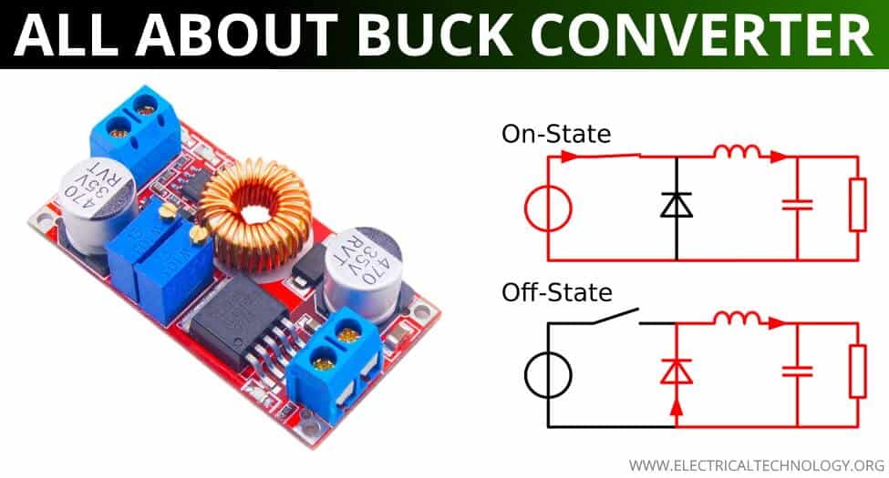
Buck Converter Circuit Design Operation And Examples

Online Simulator Validates Buck Converter Output Error Budget Analysis

Buck Converter Design Tutorial Complete Equation Derivation And Design Sample
Sepic Converter Design Buck Boost Converter Design


Inductor Calculation For Buck Converter Ic

Buck Boost Converter What Is It Formula And Circuit Diagram Electrical4u
Passive Filter Design Concept Of Buck Regulators For Ultra Low Noise Applications Article Mps

The Calculator Diy Dc Dc Boost Calculator Adafruit Learning System

Buck Converter Design Tutorial Complete Equation Derivation And Design Sample

Buck Converter Design Template Mathcad Electronicsbeliever

Buck Converter Design Template Mathcad Electronicsbeliever
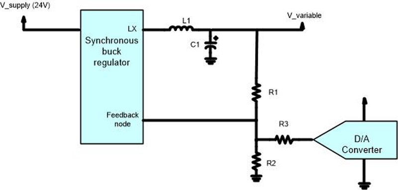
How To Design A Variable Output Buck Regulator
Basic Calculation Of A Buck Converter S Power Stage Richtek Technology

Modeling And Control For A Current Mode Buck Converter With A Secondary Lc Filter Analog Devices

Buck Converter Design Tutorial Complete Equation Derivation And Design Sample

Power Supply Design Notes Simulating A Buck Converter Power Electronics News

Capacitor Calculation For Buck Converter Ic

Buck Converter Design Tutorial Complete Equation Derivation And Design Sample
Https Www Ti Com Lit Slva882
Post a Comment for "Buck Converter Design Calculator Online"